EVAL-CN0565-ARDZ
Electrical Impedance Tomography Measurement System.
Overview
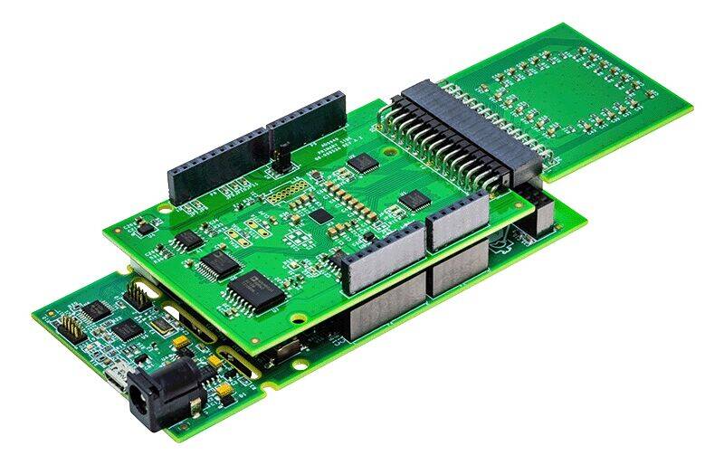
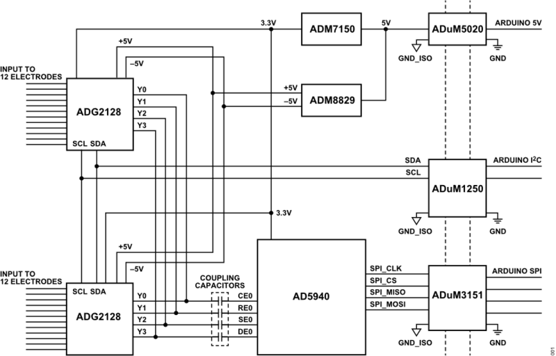
The EVAL-CN0565-ARDZ is an electrical impedance tomography (EIT) measurement system for characterizing and computing interior impedance of surfaces. The platform allows a conductivity map to be reconstructed using several repeating measurements from electrodes placed at different locations. It supports impedance measurement setups with up to 24 electrodes. The design uses a pair 8x12 analog crosspoint switches, which enables the excitation signal to be applied to one pair of electrodes at a time. The implementation of crosspoint switches allows the circuit to maximize the impedance measurements, which consequently improves the resolution of the constructed images.
The design also features a complete power and signal isolation to the host controller, which can be used as reference for bioimpedance applications. The board comes in an Arduino-compatible form factor and includes an industry-standard software interface, allowing easy integration to end-user systems as well to connect up to external development platforms such as the EVAL-ADICUP3029.
Features
Supports 24 impedance input, arbitrarily assignable to quadrupole impedance measurement channels
Supports impedance measurement setups with up to 24 electrode pairs
Accepts measurement frequency range from 0.015 Hz up to 200 kHz
Provides measurement ground that is fully isolated from host computer, with 0.47 µF isolation capacitance
Hardware Configuration
Connectors and Jumpers
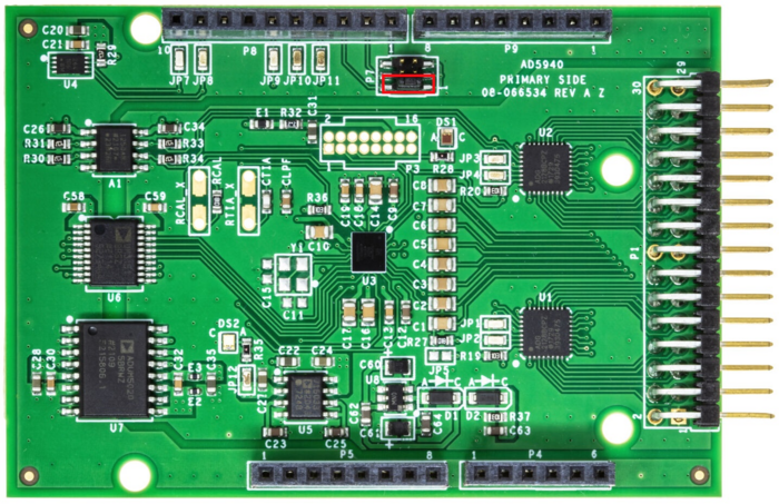
P7 (Chip Select Mapping) - leave this at default setting for the provided firmware
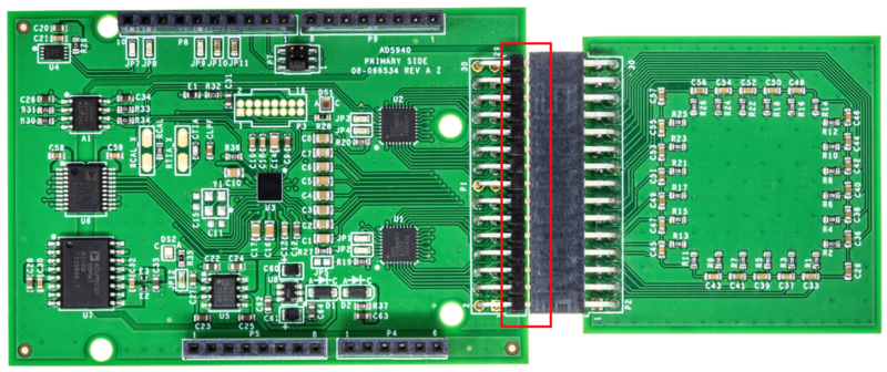
P1 (DUT Connections) - shows the pin mapping diagram
System Setup
Documents Needed
Demo Requirements
Hardware
Host PC
Micro-USB Cable
Software
Hardware Setup
Getting Started
Follow below steps to set up the hardware for testing:
Check visually if Pins 1 and 2 on the P7 of EVAL-CN0565-ARDZ are shorted by default.
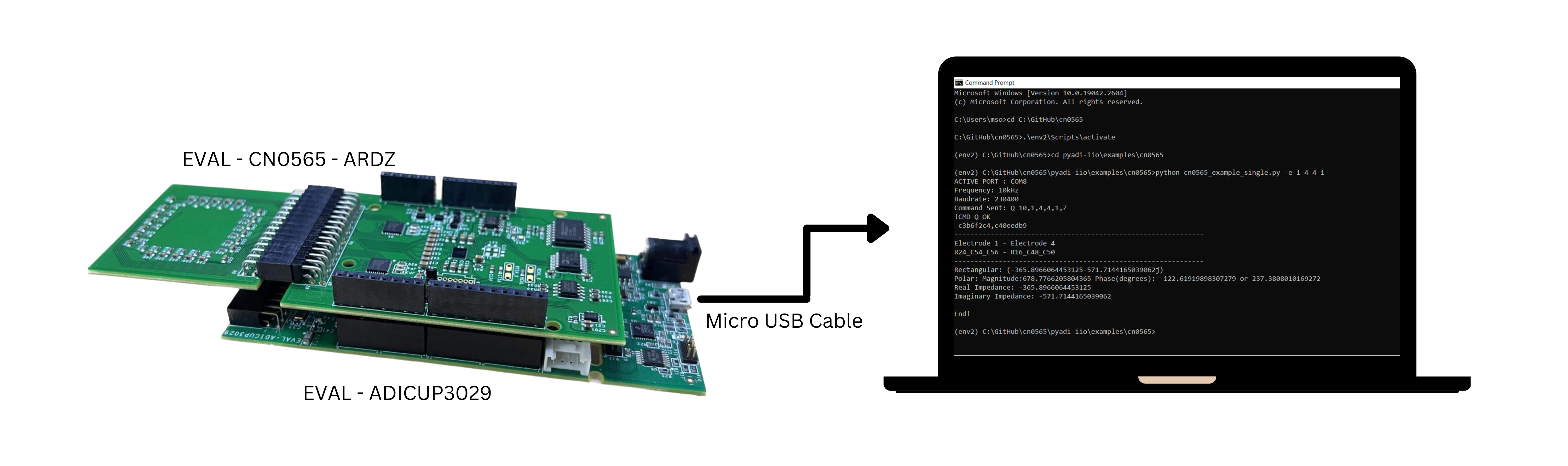
Connect the EVAL-CN0565-ARDZ (via male header pins) to the EVAL-ADICUP3029 (via female header pins). Ensure that the header pins between the two boards fit properly together.
Connect the EVAL-ADICUP3029 to the host PC using a micro-USB cable. The DS2 LED in the EVAL-CN565-ARDZ should turn green, this indicates power.
Upload the CN0565 firmware to the EVAL-ADICUP3029 by copying the prebuilt .HEX file directly into the DAPLINK drive.
Drag and drop the CN0565.HEX file to the DAPLINK. The DAPLINK will automatically disconnect and connect again, this indicates successful uploading.
Note
Ensure that the DAPLINK is visible in the file explorer, this indicates a proper connection between the EVAL-ADICUP3029 and the host PC.
Software Setup
Python Installation Guide
Assumes a fresh installation of all required software
Download the Latest Version of Python. Choose the latest available version depending on the operating system.
Run installer as Administrator. During installation, check Add Python version to PATH before clicking Install Now
To check if the download is successful, go to command prompt and type the command line below:
python --version
Installing Libiio
Libiio is a library that has been developed by Analog Devices to ease the development of software interfacing Linux Industrial I/O (IIO) devices.
Download and install the latest release of libIIO Libiio Latest Release
Install the libIIO bindings through pip
pip install libiio
Install the PyADI-IIO through pip
pip install pyadi-iio
If you need to update/overwrite your PyADI-IIO through pip, use the command below:
pip install -U pyadi-iio
Uploading the HEX File
In order to use the EVAL-CN0565-ARDZ with the EVAL-ADICUP3029, you must upload the CN0565 HEX file. The procedure is as follows:
Open the file explorer in the Host PC (Windows)
Open the folder where the CN0565.HEX file is located. If you don’t have the HEX file, download this file:
Download
Launch another file explorer, and then open the DAPLINK folder.
Drag and drop the CN0565.HEX file into the DAPLINK folder. The window will automatically close and temporarily disconnect the EVAL-ADICUP3029, and then reconnect again. This is an indication that the HEX file is properly installed.
Installing Software Requirements
Clone the example firmware from GitHub EVAL-CN0565-ARDZ Python Scripts. This includes the .txt file that contains the required modules and libraries to run the example scripts.
In Windows, open a command terminal. Point the current working directory to the cloned pyadi-iio repository by changing the directory using this command:
cd <folder address>
Navigate inside the pyadi-iio folder and install the following requirements using these commands:
pip install -r requirements.txt
pip install -r requirements_dev.txt
pip install -r requirements_doc.txt
pip install -r requirements_prod_test.txt
To test the source as a standalone module, enter this command:
pip install -e
After installing the required modules and libraries, launch the device manager and check for the active COM port where the board is connected. In the pyadi-iio folder > examples > cn0565, this is where the script is saved. Change the COM port in the script.
To run the test script, copy the address where the script is saved then enter this command:
cd <folder address>
python <file name>.py
Note
Check the active port where the board is connected in your device manager.
cn0565_example.py edit on line 122
cn0565_example_single.py edit on line 24
Python Example Scripts
Two sample scripts have been created to execute EIT measurements in the EVAL-CN0565-ARDZ. The Specific Electrode Pair script allows the user to measure the impedance on a specific electrode pair, whereas the Electrode Tomography script examines the impedance of the entire test board across all electrodes.
Using the Specific Electrode Pair Script
Open the command terminal and direct the current working directory to where the example script is saved.
Run the script by entering this command:
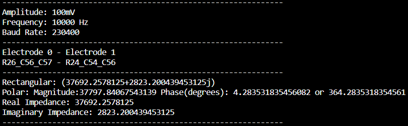
python cn0565_example_single.py
python cn0565_example_single.py 0 1 1 0
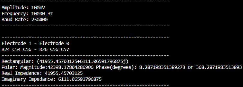
Prompting these commands in the terminal will give you the Amplitude, Frequency and Baud Rate, Electrode Pair, Rectangular and Polar Form Impedance, and the Real and Imaginary Impedance for the specific electrode pair.
Note
The numbers 0, 1, 1, 0 indicate the electrode positions for Force Leads: F+, F-, and Sense Leads: S+, and S-
Using the Electrode Tomography Script
Open the command terminal and direct the current working directory to where the example script is saved.
Run the script by entering this command:
python cn0565_example.py
Prompting these commands in the terminal will give you the Amplitude, Frequency and Baud Rate, Electrode Pair, Rectangular and Polar form impedance. Then, the Electrode Pair followed by the Rectangular and Polar Form Impedance and the Real and Imaginary Impedance for each electrode pair that is being measured will display.
After running the sample script, the program will prompt a question whether you like to generate a csv file that contains the raw data.
Enter Y if you want to generate a .csv file.

Enter N if you don’t need to generate a .csv file.

All python scripts used in performing this test are uploaded in the git repository. You may access the repository using this link: EVAL-CN0565-ARDZ Python Scripts.
CN0565 Graphical User Interface Test Example
Connect the EVAL-CN0565-ARDZ to the EVAL-ADICUP3029 via the Arduino headers.
Connect to the EVAL-ADICUP3029 to the host PC via a micro-USB cable.
The DS2 in the EVAL-CN0565-ARDZ must turn green to indicate power.
Upload the CN0565 demo firmware to the EVAL-ADICUP3029 by copying the pre-built .HEX file directly into the DAPLINK drive (see the ADICUP3029 User Guide).
Make sure that the DAPLINK is visible in the file explorer, indicating a proper connection between the two boards.
Drag and drop the CN0565.HEX file to the DAPLINK. The DAPLINK will automatically disconnect and connect again, which indicates successful uploading.
Open the command prompt in the Host PC (Windows).
Assuming all requirements have been installed, open a command terminal and direct to the current working directory to where the example script is saved by entering
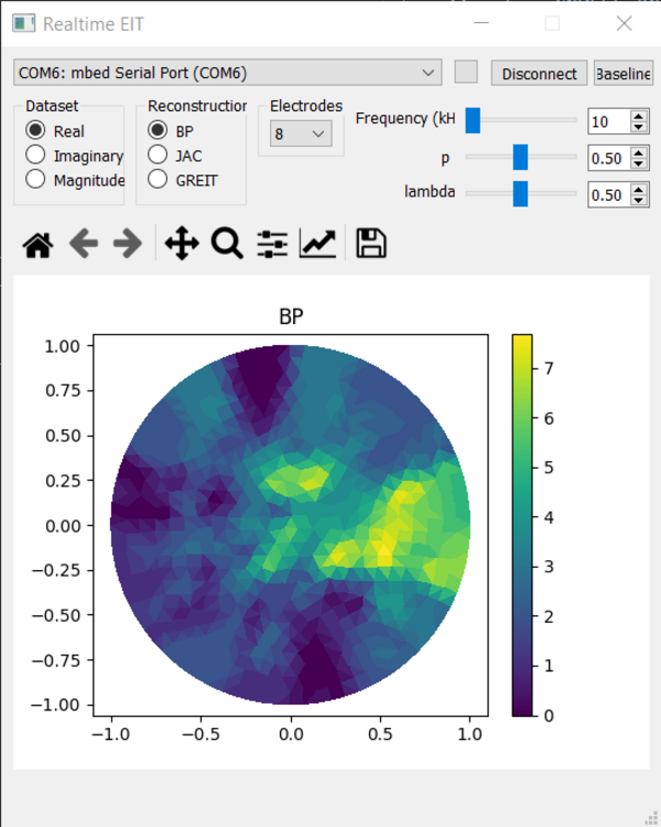
Prompt the CN0565 Realtime EIT GUI by entering this command:
Select the type of dataset, type of image reconstruction, number of electrodes, and set the frequency.
Once all the parameters are set, connect the board to the GUI by selecting Active Comport, and then click Connect. When the board is already connected, the image will automatically display.
Disconnecting the board is necessary to run the GUI for another set of measurement. Once disconnected, proceed to Step 6.
Resources
Download
Design and Integration Files
Download
EVAL-CN0565-ARDZ Design & Integration Files
Schematic
PCB Layout
Bill of Materials
Allegro Project
Help and Support
For questions and more information about this product, connect with us through the Analog Devices EngineerZone.