AD-R1M ROS2 Architecture
Overview
The AD-R1M ROS2 architecture enables the autonomous robot system, integrating CANOpen motor control, ADI Time-of-Flight (ToF) camera, IMU, and the ROS2 Navigation2 stack for 2D localization and navigation.
System Architecture
        graph TD
    K[Lift Server] <-->|/lift_cmd, /lift_state| J
    A[Drive System] -->|/odom| F[Robot Localization]
    B[IMU] -->|/imu| F
    C[ToF Camera] -->|/cam1/depth_image| D[Depth to LaserScan]
    D -->|/cam1/scan| I[Nav2 AMCL]
    F -->|/odom_filtered| G[Navigation Stack]
    E[Remote Control] -->|/cmd_vel_joy| H[Command Multiplexer]
    G -->|/cmd_vel_nav| H
    H -->|/cmd_vel| A
    I -->|/amcl_pose| G
    I -->|/amcl_pose| J[Demo Commander]
    J -->|/goal_pose| G
    G -->|/feedback| J
    G -->|/status| J
Components
Drive System and Odometry
- The robot uses multiple data sources for accurate positioning:
Motor encoders → /diff_drive_controller/odom
IMU measurements → /imu
Fused data → /odom (via robot_localization)
# Start the drive system (specify CAN interface)
ros2 launch adrd_demo_ros2 just_motors.launch.py can_iface:=can0
This motor launch starts:
- controller_manager_node
Core ROS2 control component that manages and coordinates robot controllers. controller_manager documentation
Loads and manages different controller plugins
Config: reads from
ros2_controllers.yamlcontaining:Controller configurations
Update rates
Controller interfaces
Supports both
diff_drive_controller(default) andforward_velocity_controllerfor receiving velocity commands.The active controller can be selected via the launch file (
controller:=forward_velocity_controller) and configured inros2_controllers.yaml.
# When launching just_motors.launch.py, choose between controllers:
ros2 launch adrd_demo_ros2 just_motors.launch.py controller:=<type>_controller can_iface:=can0
# Example controller configuration in ros2_controllers.yaml
diff_drive_controller:
  type: diff_drive_controller/DiffDriveController
  ros__parameters:
    publish_rate:
    left_wheel_names:
    right_wheel_names:
    wheel_separation:
    wheel_radius:

forward_velocity_controller:
  type: forward_command_controller/ForwardCommandController
  ros__parameters:
    joints:
    interface_name:
For more details, see the diff_drive_controller documentation and forward_velocity_controller documentation.
robot_state_publisher
Publishes the robot’s state (joint positions) to tf2
Computes forward kinematics and broadcasts the robot’s state
Config:
URDF model of the robot from urdf directory
Joint states from /joint_states topic
- controller_spawner
Utility to dynamically load and start controllers
Manages controller lifecycle (configured → active)
- joint_state_broadcaster_spawner
Specialized spawner for the joint state broadcaster
Publishes joint states from hardware to /joint_states topic
- robot_localization_node
Provides state estimation for robot pose
Fuses data from various sensors (IMU, odometry, etc.)
Config: Uses
ekf.yamlcontaining:Sensor inputs and frame IDs
Covariance matrices
Update frequencies
State estimation parameters
Note
The robot_localization node is configured to use the /diff_drive_controller/odom topic for odometry data, which is published by the diff_drive_controller. The EKF (Extended Kalman Filter) uses (X, Y) position, (X, Y) linear velocities, and Z angular velocity (vyaw):
odom0: /diff_drive_controller/odom
odom0_config: [true,  true,  false,   # X, Y, Z position
               false, false, false,
               true,  true,  false,   # X, Y linear velocities
               false, false, true,    # Z angular velocity (vyaw)
               false, false, false]
Using diff_drive_controller Odometry Directly (Without EKF)
If you want to use the odometry published directly by the diff_drive_controller (without fusing with IMU data via the EKF), follow these steps:
- Disable the robot_localization_node
In just_motors.launch.py, comment out or remove the robot_localization_node entry from the launch description:
return LaunchDescription([
     decl_name,
     decl_can_iface,
     decl_config_dir,
     decl_controller,
     controller_manager_node,
     robot_state_publisher,
     controller_spawner,
     joint_state_broadcaster_spawner,
     # robot_localization_node,  # <-- Comment out or remove this line
     twist_mux_node
])
- Enable odom → base_link transform in diff_drive_controller
In your ros2_controllers.yaml, set enable_odom_tf: true for the diff_drive_controller:
diff_drive_controller:
  ros__parameters:
     enable_odom_tf: true  # true: publish odom->base_link tf (set false if using EKF)
- Launch the drive system
Start the drive system as usual:
ros2 launch adrd_demo_ros2 just_motors.launch.py can_iface:=can0
With this setup, the robot will use the odometry and TF published by the diff_drive_controller directly, without sensor fusion from the EKF.
CANOpen Motor Control Integration
The EVAL-ADRD3161 motor control platform uses CANOpen for robust, real-time motor and device communication. The CANOpen configuration is managed through YAML files in the config/motors directory. Device Configuration Files (DCFs) are generated using the cogen_dcf tool, which processes EDS files and outputs DCFs for each node.
A typical CANOpen master configuration (bus.yaml) includes:
Master node: Handles the CAN bus, synchronization, and node management.
Defaults: Common settings for all nodes (e.g., product code, heartbeat, PDO mappings).
Nodes: Individual device definitions (motors), each with unique node IDs and scaling factors.
Key options:
driver/package: Specifies the ROS2 CANOpen driver for each node.
PDO mappings: Define which CANOpen objects are exchanged in real time.
Scaling factors: Convert between device units and SI units for position/velocity.
A simplified example of such configuration:
master:
  driver: "ros2_canopen::MasterDriver"
  package: "canopen_master_driver"

defaults:
  dcf: "adrd3161.eds"
  driver: "ros2_canopen::Cia402Driver"
  package: "canopen_402_driver"

nodes:
  drive_left:
    node_id: 0x16

  drive_right:
    node_id: 0x14
For detailed information on configuring CANOpen devices in ROS2, refer to the ROS2 CANopen Stack documentation and the ros2_canopen GitHub repository.
IMU (Inertial Measurement Unit)
The ADI IMU node publishes sensor data to the /imu topic using the following configuration:
- Parameters:
- iio_context_string: ‘ip:localhost’
Defines the connection method to the IMU device via Industrial I/O (IIO) framework
- measured_data_topic_selection: 2
Selects standard IMU message type for the /imu topic
Follows sensor_msgs/Imu format
- minimal_pub: true
If true, publishes only the standard IMU message without additional identification or diagnotics information
# Launch the IMU node using the above parameters
ros2 launch adrd_demo_ros2 just_imu.launch.py
For additional configuration details, refer to the adi_imu_ros2 documentation.
Note
The IMU node from the adi_imu_ros2 package publishes angular velocities and linear accelerations, but NOT orientation (Quaternion) data in the standard ROS2 sensor_msgs/Imu format. EKF (Extended Kalman Filter) is configured to use the IMU data for state estimation, see the ekf.yaml configuration file in the config directory:
imu0: /imu
imu0_config: [false, false, false,
              false, false, false,
              false, false, false,
              false, false, true,   # angular velocity in Z (vyaw)
              true,  true,  false]  # linear acceleration in X, Y
The imu_filter_madgwick node from the imu_tools can be used to fuse raw IMU data and compute orientation (Quaternion), publishing the result to /imu/data. The node subscribes to /imu/data_raw (containing angular velocities and linear accelerations) and outputs a standard sensor_msgs/Imu message with orientation. See this launch file for reference: imu_with_madgwick_filter.
The IMU is mounted to the robot using a fixed joint as defined in the URDF:
<joint name="imu_joint" type="fixed">
    <parent link="base_link"/>
    <child link="imu_link"/>
    <origin xyz="0.133 -0.01 ${wheel_radius}" rpy="0 ${pi} ${-pi/2}"/>
</joint>
This means the IMU is positioned 0.133 m forward, -0.01 m to the left, and at the height of the wheel radius from the base_link (robot center at ground-level), with a rotation of (0, π, -π/2) radians.

Figure 1 IMU coordinate frame as mounted on the robot platform. The axes (see base_link) follow the ROS REP-103 convention: X (red) forward, Y (green) left, Z (blue) up.
Time-of-Flight Camera
ADI’s EVAL-ADTF3175D-NXZ ToF sensor is used in this AMR setup to provide depth perception. For this configuration, only depth images are published and used; amplitude (AB), confidence, and point cloud outputs are disabled. The node captures depth frames from the sensor using the ADI ToF SDK APIs and publishes them as ROS topics.
- Example Python launch code:
adi_3dtof_node = IncludeLaunchDescription(
    PythonLaunchDescriptionSource(
        os.path.join(pkg_3dtof_adtf31xx_dir, 'launch',
                     'adi_3dtof_adtf31xx_launch.py')
    ),
    launch_arguments={
        "arg_enable_depth_publish": "True",  # Enable depth image publishing for LaserScan conversion
        "arg_enable_ab_publish": "False",
        "arg_enable_conf_publish": "False",
        "arg_enable_point_cloud_publish": "False",
        "arg_input_sensor_mode": "0",        # Input mode, `0:Real Time Sensor`
        "arg_input_sensor_ip": "127.0.0.1",
        "arg_encoding_type": "16UC1",        # Encoding types `mono16` or `16UC1`
    }.items(),
)
To start the ToF camera and convert depth images to LaserScan format, use the following launch command:
ros2 launch adrd_demo_ros2 just_tof.launch.py
Important: Run ~/Workspace/media_config_16D_16AB_8C.sh outside the container before starting the camera.
The camera system consists of two main components:
Camera Node
- Publishes depth images (/cam1/depth_image)
Values in millimeters
Format: 16UC1
- Publishes camera calibration (/cam1/camera_info)
Contains distortion model and intrinsic parameters
Depth to LaserScan Node
Publishes 2D laser scan data (/cam1/scan)
Converts depth images to LaserScan format
Uses camera calibration for accurate transformations
For detailed implementation and configuration, refer to the following resources:
Depth to LaserScan Parameters
Current parameters used depthimage_to_laserscan/cfg/param.yaml:
depthimage_to_laserscan:
ros__parameters:
    scan_time: 0.033
    range_min: 0.3
    range_max: 5.0
    scan_height: 200        # image height x width = 512 x 512
    scan_offset: 0.6953125  # [512 / 2 (center) + 100 (offset)] / 512
    output_frame: "cam1_adtf31xx"
The camera’s position relative to the robot base is defined in urdf/camera.xacro. Ensure the transform between cam1_adtf31xx and base_link frames is correctly specified for accurate sensor fusion and navigation.
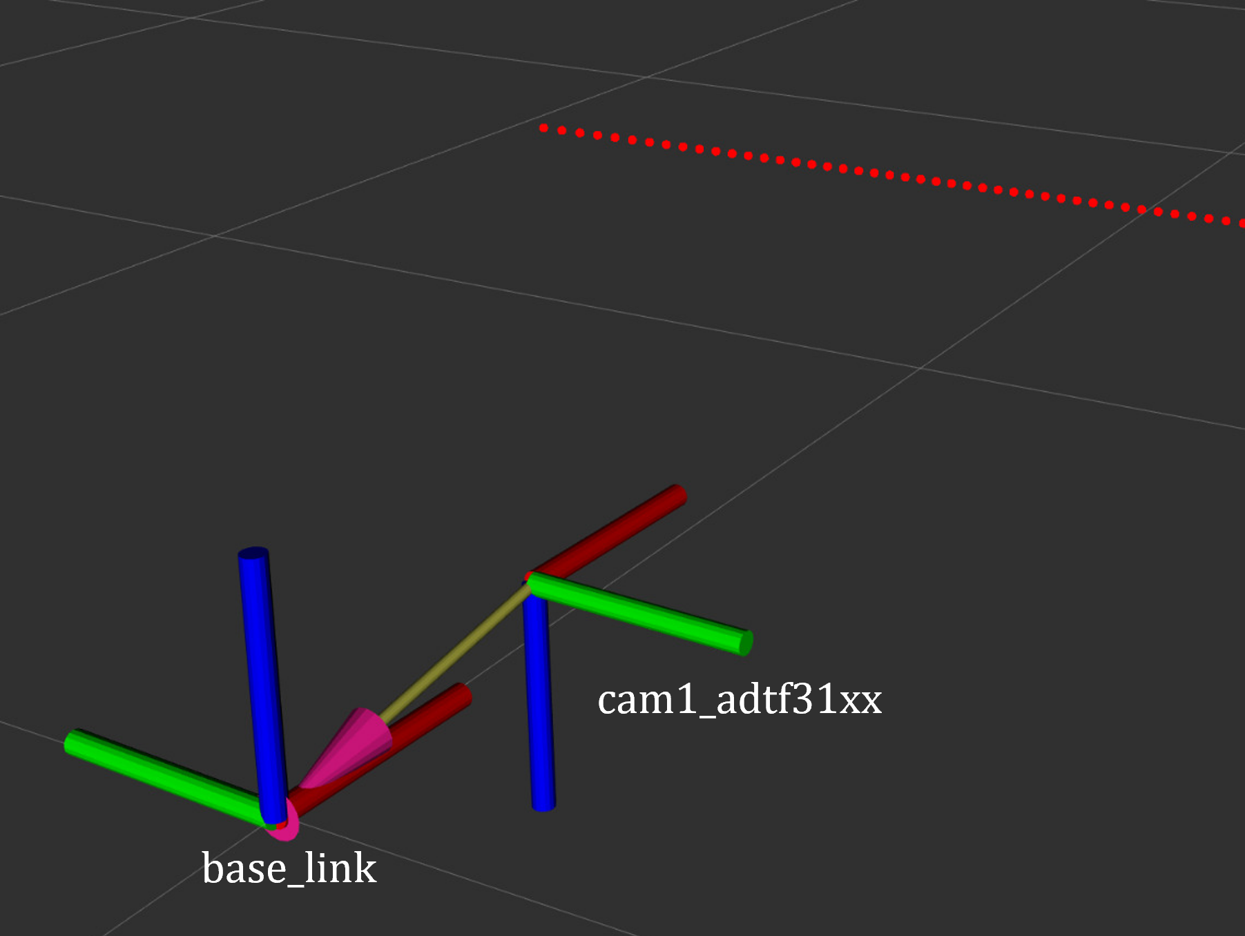
Figure 2 ToF Camera coordinate frame as mounted on the robot platform. For the current depth to LaserScan configuration, the camera is positioned at the front center of the robot chassis, slightly above the ground. The camera is rotated by π radians around the X-axis to align the Laser Scan with the robot’s forward direction, as required by the current depthimage_to_laserscan node.
The relevant URDF/Xacro snippet for the camera’s pose is:
<origin xyz="${chassis_length / 2} 0 0.055" rpy="${pi} 0 0" /> <!-- rotated for correct depthimage_to_laserscan alignment -->
Depth to LaserScan Git Versioning
The current version of the depthimage_to_laserscan package is based on the ros2 branch of the ros-perception repository, and includes features from the following pull requests:
Both PRs are merged into the ros2 branch of the currently used depthimage_to_laserscan forked repository.
Remote Control Interface
The CRSF Node is a ROS 2 node designed to interface with an CRSF transceiver, enabling remote control capabilities for robotic platforms. It integrates joystick input handling, battery telemetry, safety killswitch logic, and elevator/lifter control.
# Start joystick control
ros2 launch adrd_demo_ros2 just_crsf.launch.py
Remote Control Input (Joystick)
Processes joystick commands from an RC transmitter via the CRSF protocol
Connects to the CRSF transceiver over serial (/dev/ttymxc3, 420000 baud)
Publishes velocity commands to
/cmd_vel_joy(geometry_msgs/Twist) and/cmd_vel_joy_stamped(geometry_msgs/TwistStamped)
Safety Killswitch System
Implements an emergency stop using Switch SA on the transmitter
State machine: INIT → KILL → RUN → KILL, requiring intentional activation before operation
Automatically enters kill mode on CRSF signal loss (50+ empty reads)
Publishes killswitch state to
/killswitch(std_msgs/Bool)
Battery Telemetry
Monitors and reports battery voltage via CANopen SDO
Displays voltage and remaining capacity on the RC transmitter
Supports 3-cell battery configuration (3.0V - 4.2V per cell)
Elevator/Lifter Control
Controls a lifting mechanism using Switch SB on the transmitter
Commands: - SB Up (-90): Lift up (command 1) - SB Center (0): Hold (command 0) - SB Down (+90): Lift down (command 2)
Uses
/elevator_to_robotservice (adrd_demo_ros2/LiftGPIO)
State Machine
INIT: Startup, waits for killswitch activation
KILL: Safe state, motors stopped, lift lowered
RUN: Active, accepts joystick commands
Channel Mapping
Right Stick (rx, ry): Robot movement
Switch SA: Killswitch
Switch SB: Lifter control
Command Multiplexer
The command multiplexer node (twist_mux) combines multiple velocity command sources into a single output. It subscribes to:
/cmd_vel_joy (from the CRSF node)
/cmd_vel_nav (from the Navigation2 stack)
/cmd_vel_keyboard (from the Keyboard teleop - optional)
It publishes the selected command to /diff_drive_controller/cmd_vel_unstamped, which is used by the drive system.
Mapping and Localization
The SLAM Toolbox provides both mapping and localization capabilities, while AMCL (Adaptive Monte Carlo Localization) offers particle filter-based localization for pre-existing maps.
SLAM Toolbox for Mapping and Localization
# Start SLAM for mapping or localization
ros2 launch adrd_demo_ros2 online_async_launch.py
The SLAM Toolbox can operate in two modes, configurable in config/mapper_params_online_async.yaml:
Mapping mode: Creates new maps from sensor data
Localization mode: Uses existing maps for pose estimation
To use a pre-existing map:
mode: localization
map_file_name: /home/runner/ros_ws/src/adrd_demo_ros2/maps/<map_name>
More details on SLAM Toolbox implementation and configuration can be found in the SLAM Toolbox documentation.
AMCL Localization (Used in Nav Demo)
# Start AMCL localization
ros2 launch adrd_demo_ros2 localization_launch.py
Live AMCL localization process visualization.
Monte Carlo localization estimates the robot’s pose by subscribing to:
/odom: Robot odometry frame. Transform from /odom to /base_link is provided by the robot_localization or diff_drive_controller node./cam1/scan: Processed LaserScan depth data from ToF camera/tf: Transform tree for coordinate frame relationships
Publishes estimated pose to /amcl_pose (geometry_msgs/PoseWithCovarianceStamped), that can be tracked in RViz or by other nodes.
The AMCL parameters are configured in config/nav2_params.yaml:
amcl:
  ros__parameters:
    use_sim_time: False
    alpha1: 0.05 # rad/s -> rad/s, covariance from rotation to rotation
    alpha2: 0.05 # rad/s -> m/s, covariance from translation to rotation
    alpha3: 0.05 # m/s -> rad/s, covariance from rotation to translation
    alpha4: 0.05 # m/s -> m/s, covariance from translation to translation
    # alpha5 irrelevant for diff drive
    base_frame_id: "base_link"
    beam_skip_distance: 0.05 # reduced from 0.5
    beam_skip_error_threshold: 0.9
    beam_skip_threshold: 0.3
    do_beamskip: false
    global_frame_id: "map"
    lambda_short: 0.1
    laser_likelihood_max_dist: 0.05 # 5cm bubble around obstacles
    laser_max_range: 5.0
    laser_min_range: 0.3
    laser_model_type: "likelihood_field"
    max_beams: 180        # number of beams/rays used in the particle filter scan
    max_particles: 700    # max number of particles for localization
    min_particles: 500    # min number of particles for localization
    odom_frame_id: "odom"
    pf_err: 0.02
    pf_z: 0.99
    dist_threshold: 0.3
    recovery_alpha_fast: 0.1    # increased from 0.0
    recovery_alpha_slow: 0.0001 # increased from 0.0
    resample_interval: 2
    robot_model_type: "nav2_amcl::DifferentialMotionModel"
    save_pose_rate: 0.5
    sigma_hit: 0.02  # 2cm stddev on distances
    tf_broadcast: true
    transform_tolerance: 1.0
    update_min_a: 0.05   # 5deg per update
    update_min_d: 0.01   # 1cm per update
    z_hit: 0.5
    z_max: 0.05
    z_rand: 0.5
    z_short: 0.05
    scan_topic: /cam1/scan

    set_initial_pose: True
    initial_pose:
      x: 0.0
      y: 0.0
      z: 0.0
      yaw: -1.5708  # -90 degrees
Key parameters for tuning localization performance:
Particle filter settings:
min_particles(500) andmax_particles(700) define the range of particles used for pose estimationUpdate thresholds:
update_min_d(1cm) andupdate_min_a(5°) determine when localization updates occurLaser model: Uses
likelihood_fieldmodel withmax_beams(180) for efficient processingMotion model: Configured for differential drive with noise parameters (
alpha1-4) tuned for the platformInitial pose: Set to origin with of the provided map.
Detailed information on AMCL parameters can be found in the Navigation2 documentation.
The implementation of the AMCL node can be found in the nav2_amcl package, which is part of the Navigation2 stack.
An intuitive visualization of the AMCL localization process is explained here.
High-Level Control (Commander Nodes)
# Run a commander node
ros2 run adrd_demo_ros2 <node_name>.py
Available commander nodes:
demo.py: Basic navigation demo with elevator integration
waypoint_follower.py: Follows predefined waypoint sequences
elevator_server.py: Simulates elevator control responses
Commander nodes provide:
Integration with Nav2’s
BasicNavigatorWaypoint definition and sequencing
Robot pose management
Task coordination
Elevator integration
More details on the commander nodes and examples on how to interact with the ROS2 system can be found in the ROS2 Examples documentation.
Visualization and Manual Control
RViz Visualization
Launch RViz with the preconfigured layout:
ros2 run rviz2 rviz2 -d src/adrd_demo_ros2/rviz/main.rviz
Note
Fixed frame selection impacts data visibility:
/base_link: Only robot-relative data/odom: Robot and odometry data/map: All data when mapping/localization active
TF Tree Structure:
map
└── odom
    └── base_link
        ├── base_footprint
        ├── camera_link
        ├── wheel_*_link
        └── imu_link
Select the appropriate frame based on active components to avoid transform errors.
Manual Control
For manual keyboard control, you can use the teleop launch file:
ros2 launch adrd_demo_ros2 teleop_launch.py
This launch file provides:
- Teleop Keyboard Node
Enables keyboard control of the robot
Publishes velocity commands to /cmd_vel_keyboard
Runs in a separate terminal window (xterm)
- Killswitch Keyboard Node
Provides emergency stop functionality via keyboard
Runs in a separate terminal window
Safety control independent of joystick
Alternatively, you can run keyboard teleop directly:
ros2 run teleop_twist_keyboard teleop_twist_keyboard --ros-args -r cmd_vel:=/cmd_vel_keyboard
Important
Make sure you launched the motor system first before using keyboard teleop.
Quick Start
To quickly get the robot running, you can create a bash script to start all nodes sequentially. Here’s the recommended startup sequence:
#!/bin/bash
# Start motor control system
ros2 launch adrd_demo_ros2 just_motors.launch.py can_iface:=can0 &
sleep 20

# Start telemetry and remote control
ros2 launch adrd_demo_ros2 just_crsf.launch.py &
sleep 10

# Start sensor nodes
ros2 launch adrd_demo_ros2 just_imu.launch.py &
sleep 10
ros2 launch adrd_demo_ros2 just_tof.launch.py &
sleep 10

# Start localization
ros2 launch adrd_demo_ros2 localization_launch.py &
At this point, you can move the robot around using the remote control and observe how it localizes in RViz. The robot will track its position using AMCL particle filter localization.
To enable autonomous navigation, start the navigation stack:
# Start autonomous navigation
ros2 launch adrd_demo_ros2 navigation_launch.py &
Once navigation is running, you can publish goal poses from RViz using the “2D Goal Pose” tool. The robot will compute an optimal path and autonomously navigate to the target location.
For high-level autonomous behavior, start a commander node:
# Start autonomous mission commander
ros2 run adrd_demo_ros2 demo_run.py
The commander node provides a demo script for robot navigation and lift control with the following features:
LiftClientAsync: Asynchronous ROS2 service client for controlling a lift via GPIO
Waypoint: Helper class for storing navigation waypoints with orientation and lift actions
PoseTracker: Node that tracks robot pose, navigates through waypoints, and coordinates lift actions
Navigation Integration: Publishes navigation goals, sends velocity commands, and interacts with the lift service
See the next ROS2 Examples section for more details on how to interact with the system, refer to the ROS2 Examples documentation, which provides examples of how to interact with the robot using the available commander nodes and other ROS2 features. For more information on the AD-R1M ROS2 architecture, refer to the AD-R1M ROS2 GitHub repository.