< go back to the blog article list
trupples' blog
Making a 6 bit CPU
This project has been on hold for quite a while. I really hope I'll get to continuing it someday
Day 1
TL;DR - ICs got delivered; RS latch; not enough wires and breadboards
First thing after getting out of school I got a call from the courier telling me he had the order. Yay!
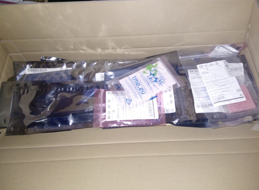
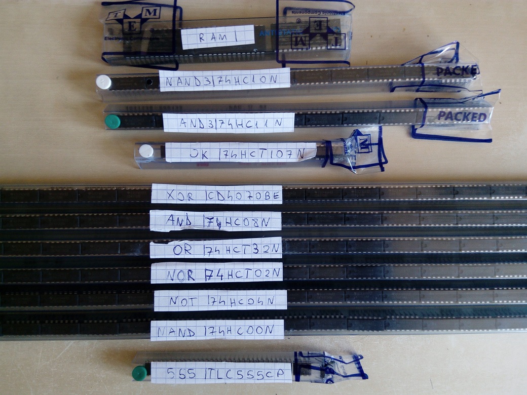
After unpacking everything, I labeled the long IC tubes so that I don't have to keep the bag labels or have to read the brown on black serial number on the chips themselves. And yes, I know I'm going to have to use pull up and pull down resistors everywhere because I'm mixing HC with HCT with LS series. I was dumb enough not to research before buying >.<
To try these out, I made one of the simplest circuits there are, the RS latch. I'm using an Arduino Nano clone as a power source.
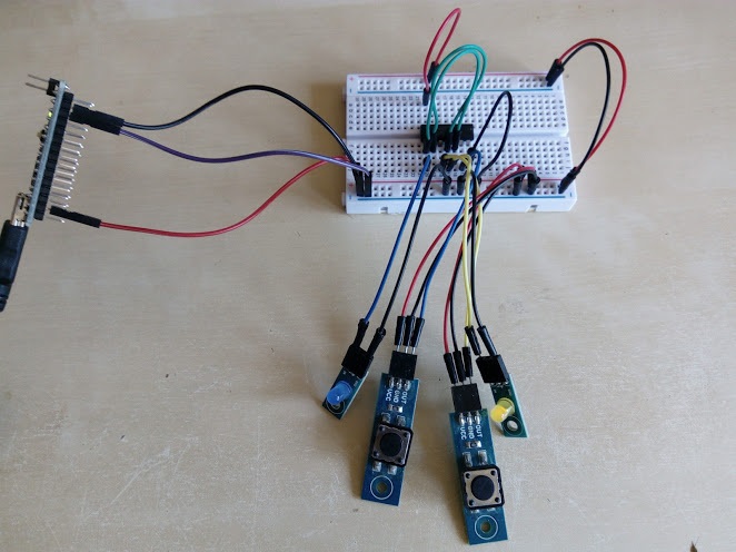
I then realised that my project will become an absolute rat's nest if I continued using dupont-like cables instead of cutting fixed length, flush with the breadboard ones from a big coil. Too bad I don't have a big wire coil, nor capacitors for the 555 clock, nor enough resistors for all the pull-ups, nor enough breadboards. This means that the project will be on halt for 2 days because it's friday night and all hardware stores near me are closed in the weekend.
Well, not really. I can still plan stuff in these two days.
Planning the thing
All the mistakes!
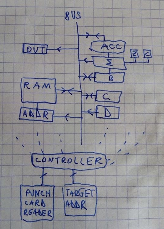
When I started planning, I realised I forgot to order a ROM chip for the instruction decoding. This led me to decide to use punch cards for the program memory because punch cards seem really cool. I really hope I won't regret this too much. I also forgot to get some demuxes so I'll need to keep decoding binary to multiple lines to a minimum. These two are the reason the punch cards will be very wide.
Word length
I chose 6 as the word length. I wanted something greater than 4, but 8 seemed a little too big. On one hand it would add a few centimeters to the punch card width and on the other it would probably require a few more breadboards and stupid amounts of transistors for the hopefully few decoders I'll need. That won't work for me because I'm really cheap. 7 bits would've probably worked but 7 is odd and I have some standards. 6 bit words seem just right. A 6 bit charset is big enough to fit letters, digits and a few symbols. 64 instructions is not a bad limit at all, really, and the shopping basket won't get bigger than what I mentioned at the end of the last section.
Punch card format
I settled on 3 instructions: MOV, SUM and JMP. The 6 PC bits are there to remove the need for PC logic.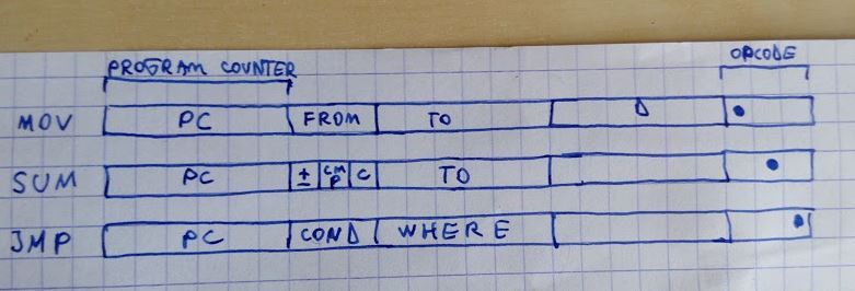
The MOV instruction takes a binary FROM value being the register to read, 6 TO bits representing the places the value will be moved to (can be multiple) and 6 bits that will be the value of the read-only D register for moving literal values.
The SUM instruction takes a sign bit (addition or subtraction), a CMP bit which dictates if the Z and C flags are set, a Carry bit, which if high XORs the carry in with the last operation's carry out and a TO part which works like the MOV TO.
Lastly, the JMP instruction takes a 3 bit condition and a 6 bit address. This sets the controller's "target address" register to that address, making the CPU cycle through the punch cards until that PC value comes up.
Day 2
Made this file and typed in the "journal".Day 4
Got a few meters of wire, 5 breadboards, a few caps and a decent amount of resistors (though I think I'm going to need more).Day 5
Started work on the adder. Realised that wiring is a total pain in the ass and that I'll really have to work on that to get Ben Eater-level neato burrito breadboards.
The logic gate ICs just fit on a single breadboard and I'm going to need to implement the B negating on another board. ATEOTD I have a 1bit full adder. The first 3 ICs (from the left) are CD4070BE XOR gates, the next 3 are 74HC08N AND gates and the last 2 are 74HCT32N ORs. Tomorrow I want to get the jumper wires out of there and use the neater kind and to wire at least 2-3 more bits to the adder.

Day 8
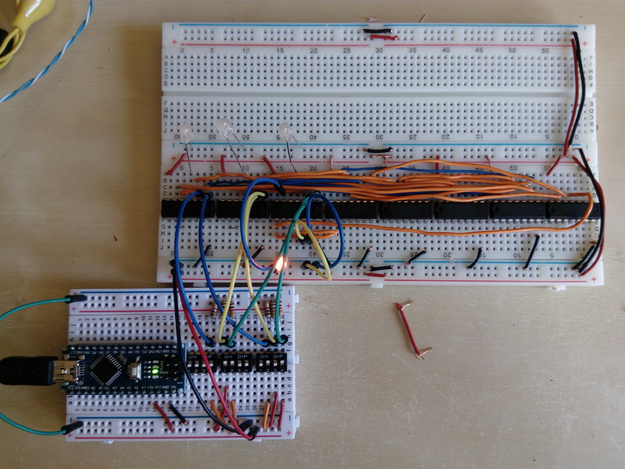
After 2 days of feeling sick, I got to working on the CPU again. While using multi-strand wires is a total pain in the ass, solid ones are such a breeze to work with. I managed to make 4 bits w/o the last one's carry working by 3PM-ish:
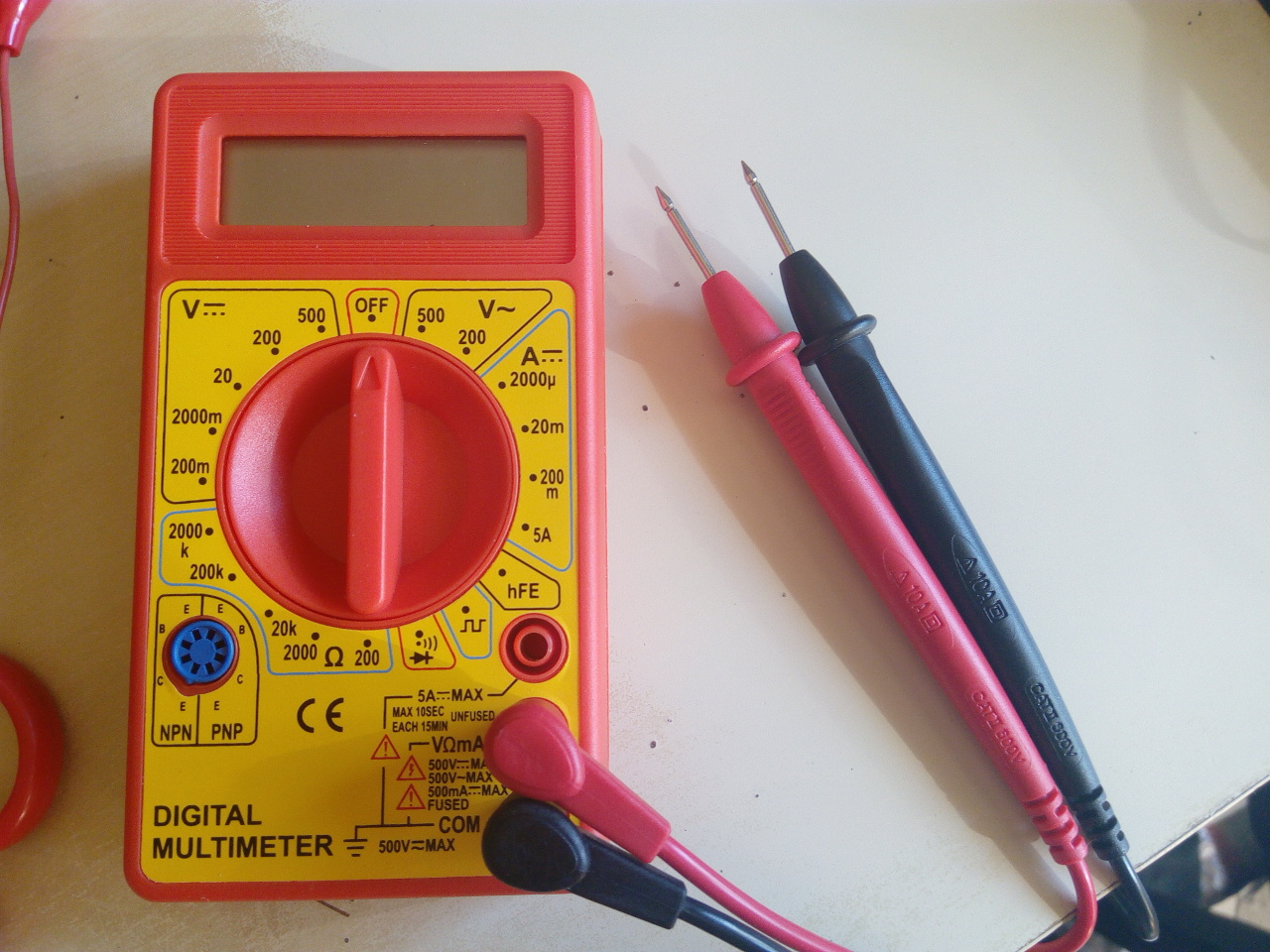
A multimeter is also a very handy tool because now I don't have to connect LEDs everywhere I want to test what's on a wire or consult the resistor color code chart (that I don't remember) all the time.
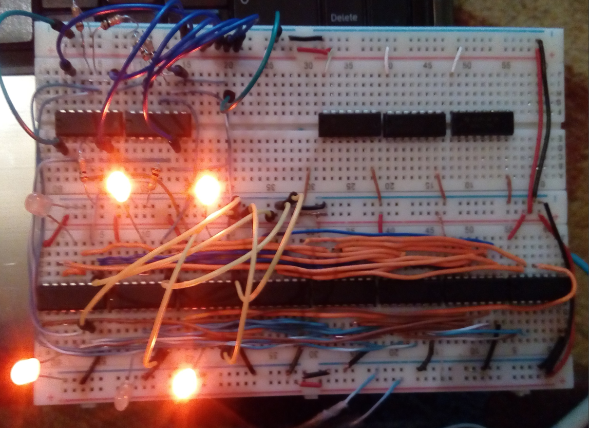
FFWD a few hours and I have the whole adder working. Next on the todo list is
the add/subtract/compare logic. In the image I'm calculating 24 + 51 = 11 (after
overflowing). The top 3 LEDs are the 3 least significant bits, the bottom left 3
are the most significant 3 digits and the bottom right is the overflow flag w/o
a curent limiting resistor because
Day 14
I really have no better excuse than lazyness to not having worked on the CPU for so long :/
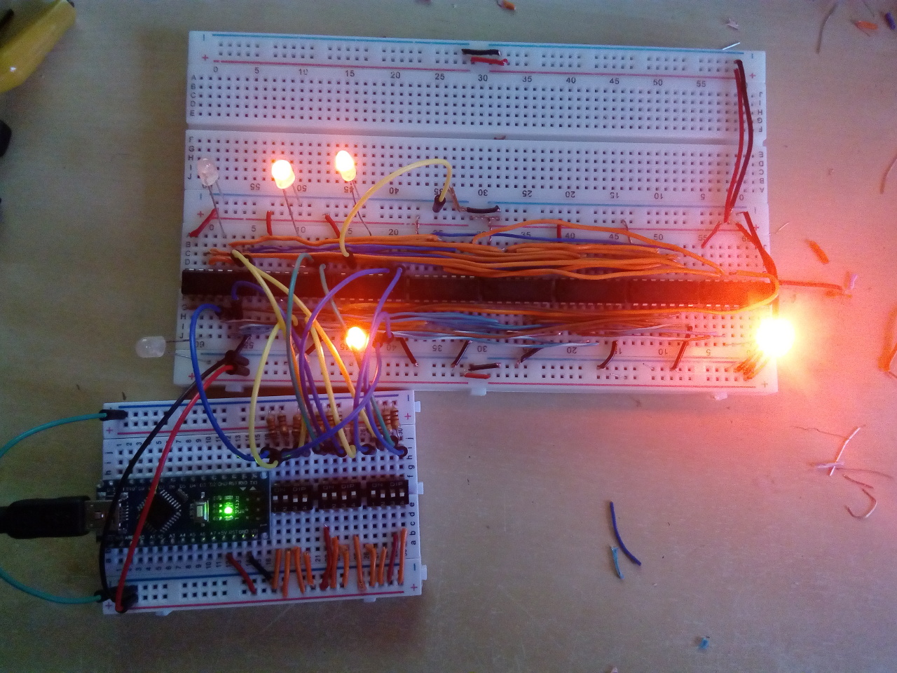
Anyways, here's the ADD/SUB logic (just 7 XORs, meh). During the making of this module the inconvenience of pull-down resistors became really apparent as I had to mix different family ICs. This chart is hella useful by the way. The left image shows 28+15=43 being calculated and the second shows 28-15=13, but I only needed to move ONE wire to do that :D
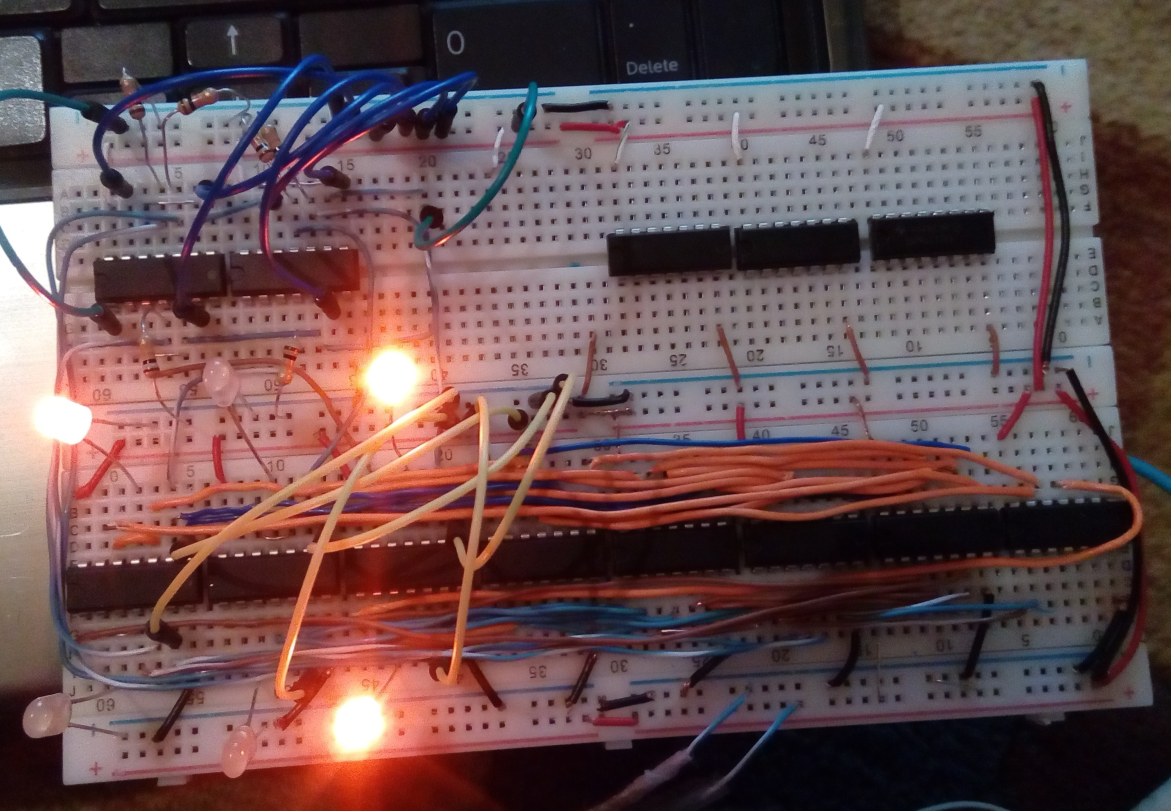
The 3 ICs on the top right are an XNOR, 3-input AND and D latch for the zero flag computation and for storing the zero and carry flags.